Techniques for Flexible Circuit Boards
As the demand for flexible circuit boards grows, manufacturers must be prepared to use a variety of assembly techniques to ensure that the products produced meet quality standards. These processes are often different than those used in rigid PCB fabrication, primarily because the components attached to flexible circuit boards must be able to withstand more extreme conditions. Some examples of these extreme conditions include repeated flexing, heat, and humidity. This has led to the development of specialized assembly processes for this type of board.
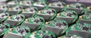
The most common method for mounting components to a flex circuit board is SMT (Surface Mount Technology). This involves printing solder paste on the surface of the bare board, then using high-speed pick-and-place machines to place the component parts at their designated locations. The soldering process is a key part of the circuit board assembly, and it must be done properly to avoid damage to the flex circuit.
Another assembly technique that can be used for a flexible circuit board is through-hole technology. This is a manual process that requires the use of special soldering equipment and a highly skilled team. While through-hole technology is typically less expensive than SMT, it does require a longer manufacturing time and is more likely to result in errors than other types of assembly.
Assembly Techniques for Flexible Circuit Boards
In some cases, a hybrid construction flex circuit board may be the best solution for a project. A rigid-flex circuit is a combination of two or more rigid boards electrically connected through a series of flex sections. The conductive copper layers of the rigid boards are sandwiched between flexible polyimide coverlays and an adhesive layer. The flex sections of the rigid-flex circuit board can be configured in several ways, including symmetrical construction, which uses an even layer count. Rigid-flex circuits also support odd layer count configurations, which can be useful for reducing the size of the traces to maintain impedance control and EMC requirements.
When designing a flexible circuit board, the engineers must make sure to take into account the maximum possible bend radius. This will help them select the appropriate materials and stack-up for the assembly process, as well as determine how much stress is placed on the flex sections. To reduce the potential for stress-induced failure, it is also important to make sure that the traces in the flex section are not too close together, as this can cause stress concentration at one point.
To prevent this, the designers should design the flex sections to have offset conductors. This will help to minimize stress on the flex sections during bending and allow the flexibility of the circuit board to be maximized. In addition, it is critical to choose an adhesive that will be long-lasting and capable of surviving the assembly and reflow soldering processes.